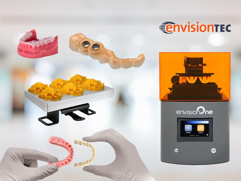
There's only one EnvisionOne...Today, there are numerous 3D printing options with advertised prices under $10k in the dental market. These may seem like a good option, especially as entry models, for a low-cost investment into 3D printing for your office, but is that truly the case when your professional reputation is associated with the quality of appliances your office is producing? Besides, cost is only one factor. Build accuracy, speed, capacity, printer durability / reliability, as well as variety and quality of available materials are additional factors that should be considered by any office looking to incorporate a 3D printer into their digital workflow.
In order of importance, here are some of the critical areas where these low cost machines fall short:
At a price of under $20k (as of Feb 2020), the EnvisionOne is one of the most advanced 3D printers on the market with a model specifically designed for dental applications, and several benefits in all aforementioned areas vs. dental SLA/DLP printers.
1 Comment
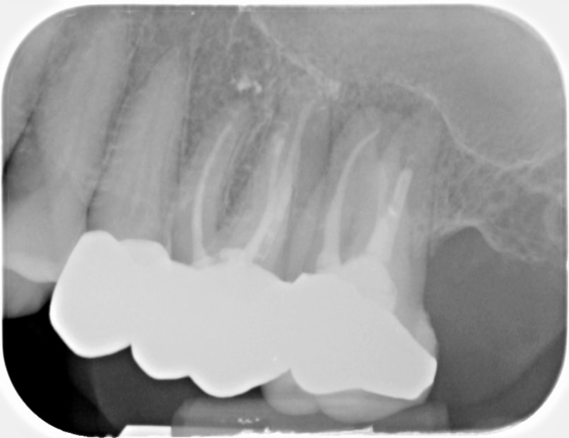
To be the best diagnostician you can be, you'll want to ensure you are equipped with imaging modalities that can provide a holistic view of anatomy. Our client, Dr. Nivine Y. El-Refai, BDS, DDS, MSD, recently shared a case that highlights the diagnostic advantages that 3D CBCT has to offer. Dr. El-Refai's case summary is italicized below: Patient was referred to my office for retreatment of #14. The PA showed hazy RL related to both #14 & #15. The patient was tender to biting, percussion & B palpation on both #14 & #15. CBCT was taken to evaluate the root canal filling in both teeth & locate any untreated canals. Thanks to the CBCT, I was able to determine that the origin of the infection started from #15 and was starting to spread to DB root of #14. #15 had been previously retreated and had poor prognosis. The patient decided to get #15 extracted and observe #14. One week after extracting #15, the patient was totally asymptomatic and all tenderness related to #14 disappeared. Thanks to the CBCT, the patient did not have to go through a retreat of #14, which would not have resolved her symptoms.
The LFV Morita X800 is an excellent aid for proper diagnosis. With the new decade fast approaching, you and your staff should be aware of and prepared for an important update regarding Windows 7 in 2020. Specifically, that the operating system (OS) will no longer be supported by Microsoft. This means no more security patches, bug fixes, or technical support, and that (because of this lack of updates and support) the OS will no longer be compliant with HIPAA. To ensure security and HIPAA compliance, offices that are still using Windows 7 will need to take action on one of the following options regarding Windows 7 PCs: Enroll in Microsoft's Extended Security Updates (ESU) ProgramAccording to Microsoft, ESU packages may be purchased for Windows 7 to extend critical security updates for the OS through January of 2023. This would allow offices to continue receiving critical updates and support for Windows 7, and keep their PCs in compliance with HIPAA. If your office would have difficulty transitioning to Windows 10 machines before the end of the year, ESU packages will be your best option to ensure security and compliance entering into 2020 and beyond. Upgrade your software (and hardware) to Windows 10This option is what we recommend to any office who doesn't have an extremely compelling need to remain on Windows 7. Not only will Windows 10 remain compliant with HIPPA for several years to come, it is also more secure and allows greater speed and functionality than any Windows 7 system moving forward. Before upgrading your software to Windows 10, it is crucial that you have your IT partner assess your office's computers, as many may need to be replaced to function properly with the new OS, and to continue to be reliable for your practice. Many offices with older PCs will be better off upgrading to new PCs that come pre-loaded with the new OS and updated components to keep them on the cutting edge of the obsolescence curve. Connect with Dental TIAre you unsure what option is most appropriate for your office? Connect with Dental TI today to discuss a plan for your office's technology moving forward. This sort of transition can be stressful, but it doesn't have to be! In fact, upgrading can often create opportunities to implement more efficient workflows. Contact us today to learn more about how we can help your practice reduce downtime, increase productivity, and optimize diagnostic image quality!
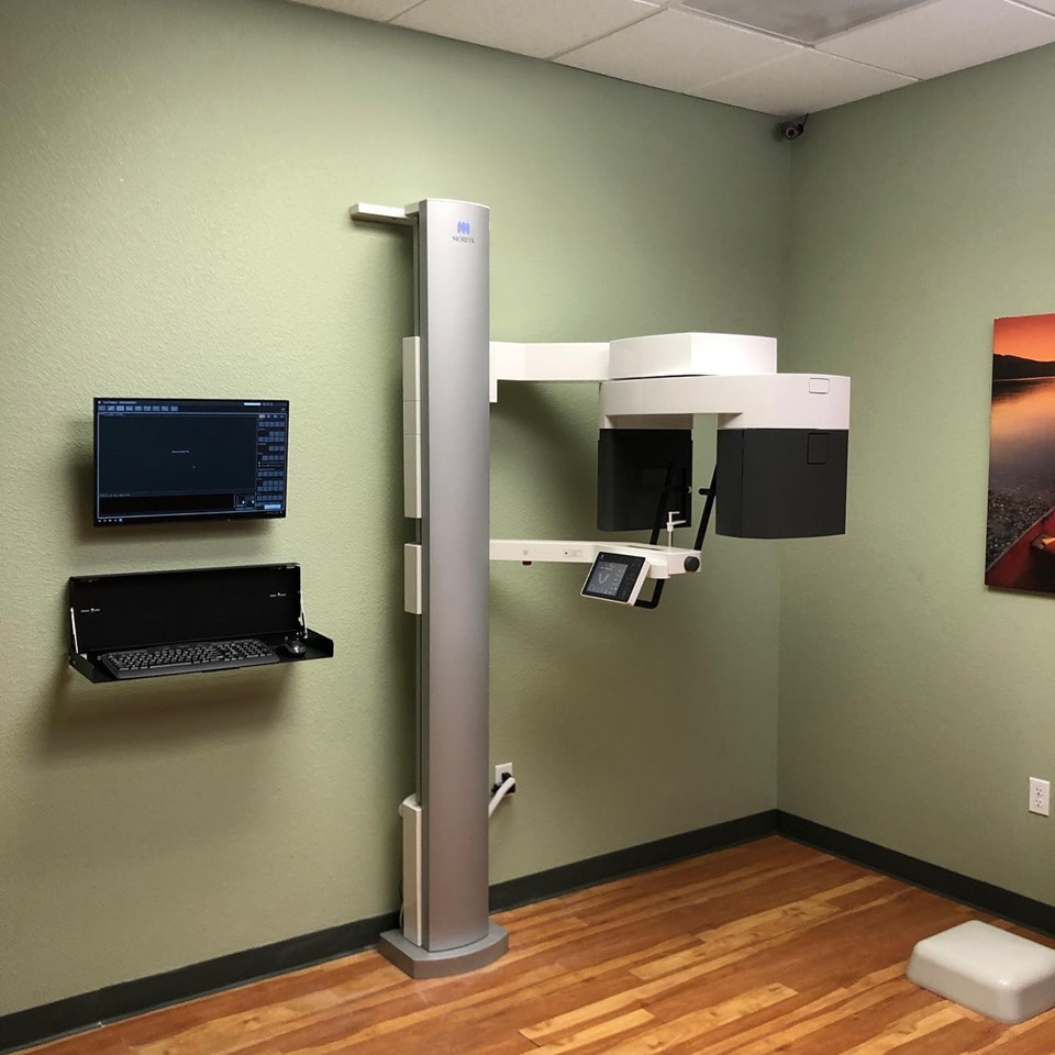
CBCT is a major investment for a dental practice, and offers the potential to provide significant boosts to production and profitability. It is important that you not only identify the right CBCT system for your practice, but also the right company to provide it. CBCT systems are delicate, highly precise units-- shouldn't the company installing them have the expertise and experience to place the unit where it will be accessible, compliant, and aesthetic? Here are important aspects of any good CBCT install that you should make sure your provider includes. Spoiler alert: with Dental TI, all of these aspects of an installation are included, free of charge. Before the install:Well before your installers ever arrive, they should create an "installation plan" showing the room where the unit will be placed; its orientation; placement of any required outlets, conduit, or wall-backing; the acquisition PC location; and the location of the exposure switch. This installation plan should also be sent to a licensed physicist to create a "shielding report" based on the scatter plot of the CBCT system to be installed which states whether or not any additional shielding will be required to satisfy local regulations. In a few states, this shielding report is not required, but those states are the exception to the rule. During the install:CBCT installation is a long process; be wary of any company who claims they can do the job in under 5 hours. Once the new unit is loaded into the practice, and the area is staged for its installation, the first step is typically to ensure wall-backing has been placed, or that there are studs that the unit can be anchored to. Once the unit is up, a good installation will run all power and communication cables through the wall for the best possible aesthetics and wire concealment. Unless a specific counter-space or desk has been identified for the location of the acquisition PC, the PC, monitor, and keyboard should all be mounted flat to the wall. The acquisition switch should be placed far enough away to ensure the operator is not exposed to scatter radiation. If a clear line of sight to the patient cannot be maintained, a mirror or webcam should be installed to provide a visual of the patient while scans are being taken. If you want to make sure that your CBCT system will be installed with the highest level of attention paid to the important details: accessibility, compliance, and aesthetics, we recommend purchasing from Dental TI. Feel free to contact us at any time to discuss your imaging plans for 2020 and beyond!
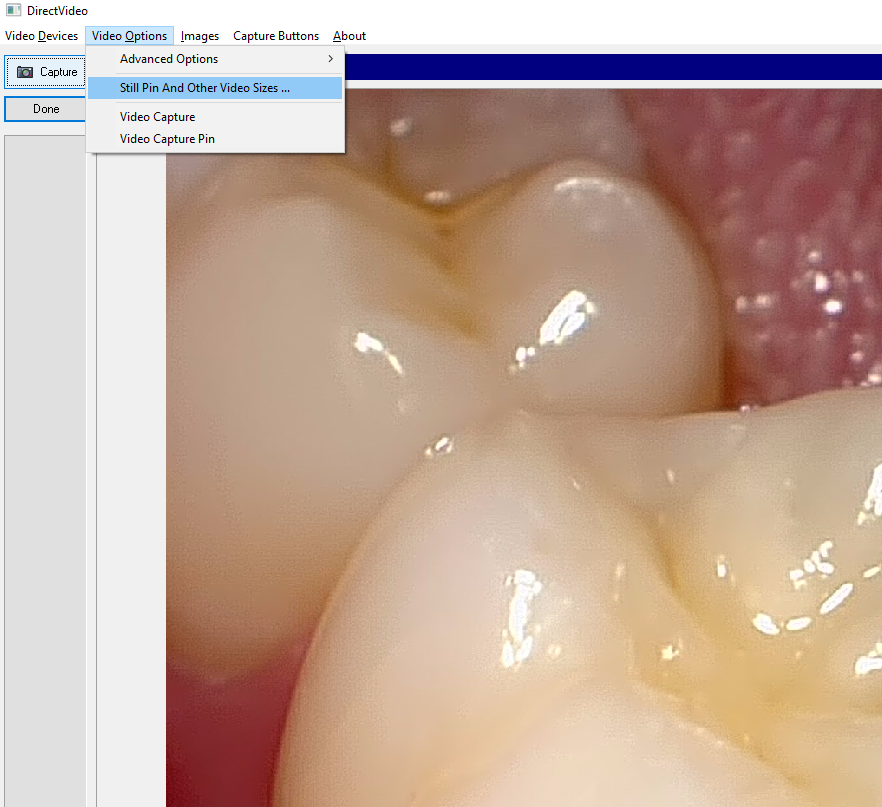
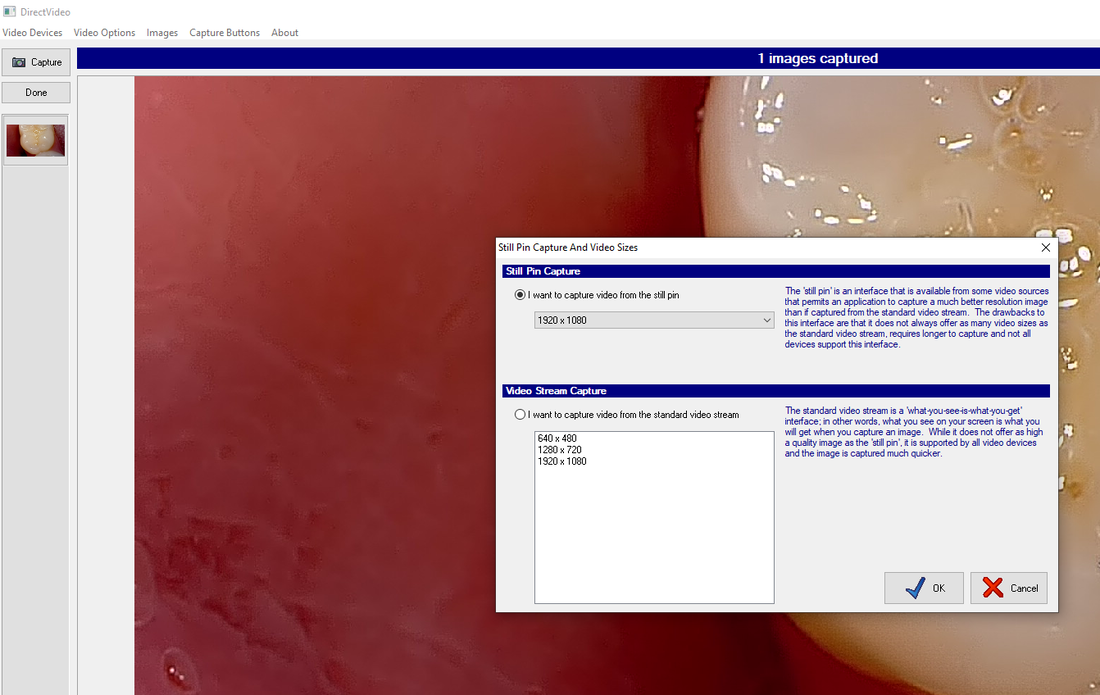
To see more examples of great CBCT installations, check out Dental TI's Instagram profile! Another common Apteryx support call we receive from offices stems from a situation where the capture button on their camera doesn't seem to work. They have a live video stream, but nothing captures when they press the button. For most intraoral cameras, the solution is very simple: make sure the camera is set to capture from the still pin. Here's how: Once you have ensured the Still Pin is selected, and you have the proper resolution set, simply hit "OK", and you are ready to capture. If you are a client and are having difficulty, don't hesitate to contact us for free support!
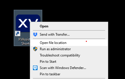
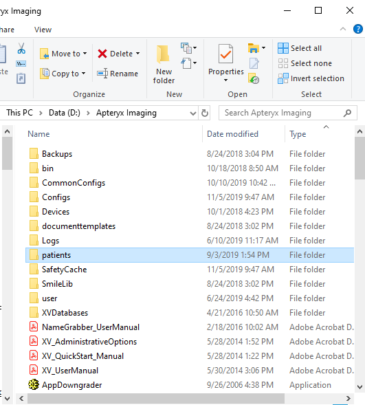
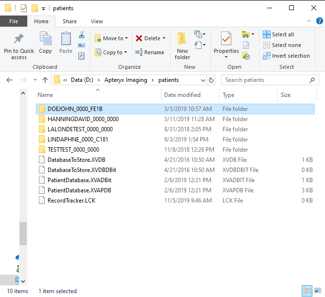
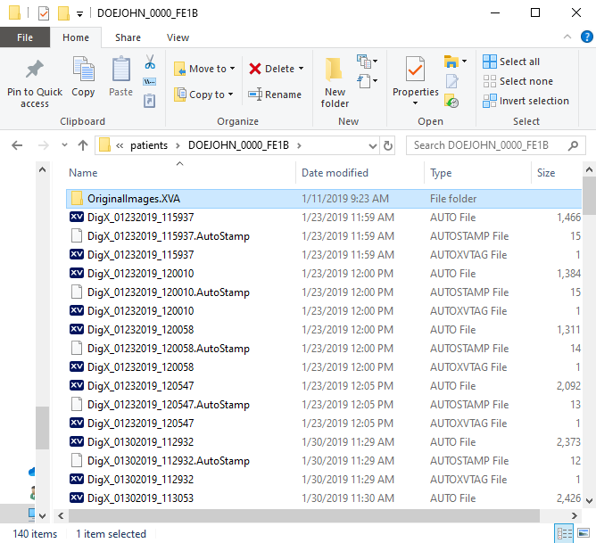
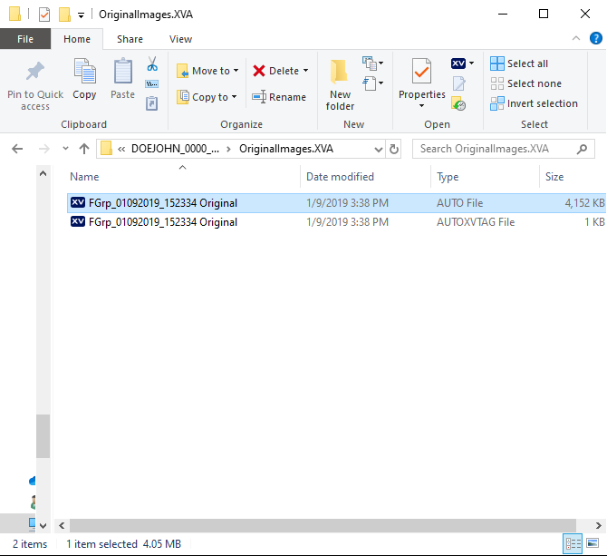
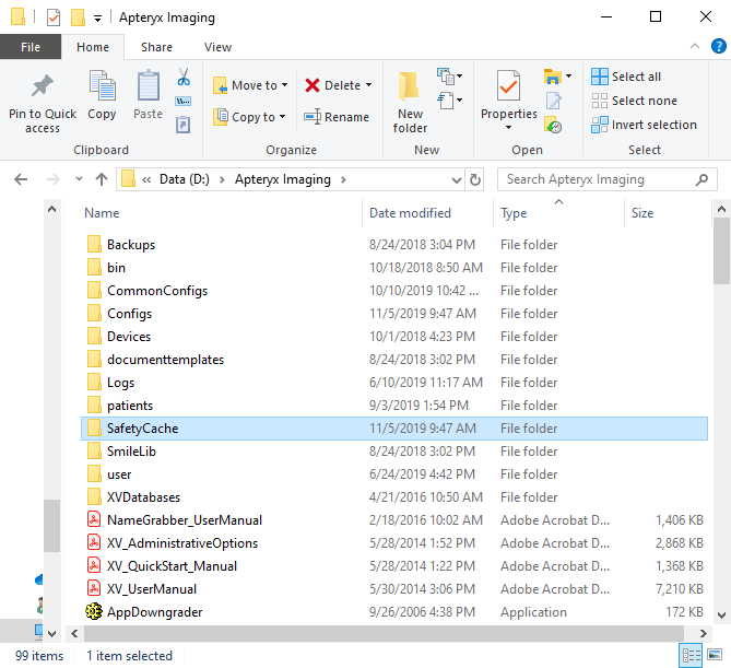
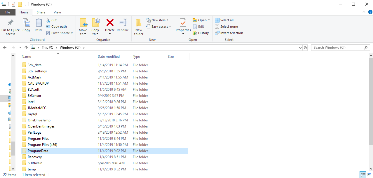
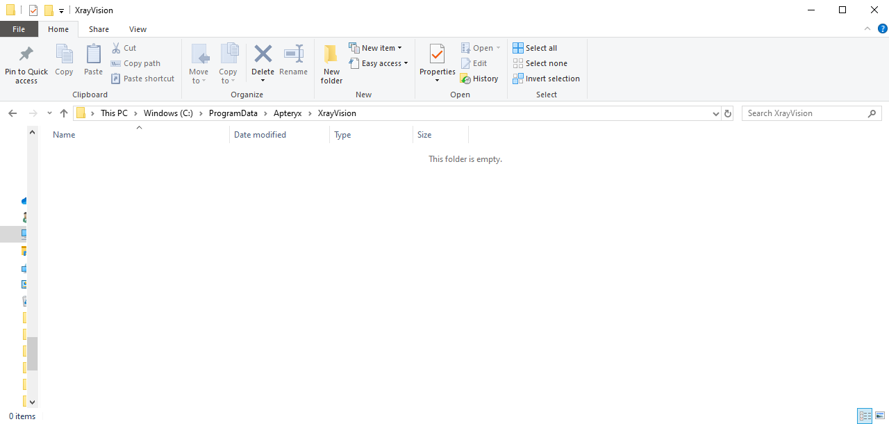
Dental TI has recommended Apteryx Image Management software for years. It is a great program that interfaces directly with imaging hardware from more manufacturers than any other dental imaging software that comes to mind. It integrates smoothly with just about any other practice management, image management, 3D, and document editing software under the sun, and offers robust functionality for acquiring and presenting radiographic and photographic patient images. One common support call we receive from clients involves images that are missing from a patient's file. Usually, this occurs when a patient is open in multiple rooms, one of their images is adjusted (i.e. brightness/contrast adjustment), and then those changes are not saved properly when the software prompts the user to do so. Other times, a staff member may have deleted an entire layout when trying to delete a single image or blank tile. Whatever scenario has caused the images to go missing, here are the places to go searching for the missing x-rays or intraoral camera images, starting with the first place an office should look. First, check the patient's "Original Images" folder. (On any office PC)XrayVision stores "original images" which are original versions of acquired patient images in a sub-folder of the patient's folder in the program's folder... Woof! Don't worry; it's easier to locate than it sounds. First, right-click on your Xray Vision shortcut on your desktop and select "Open file location": Next, find and select the "Patients" folder in the Apteryx folder: Now, find and select the patient's folder. You can use the search bar in the upper right corner to find a patient's name more quickly in a large database. In our example, we are looking for missing images for "John Doe": Select the "Original Images" folder: Finally, find and highlight all the files in Original Images that correspond with the date(s) the images were originally acquired. Right click and copy those files, then go back to the patient's folder and paste the files back in. Did the patient not have an Original Images folder in their patient folder? Were there no files in their Original Images folder that corresponded to the right date? Here's where to look next: Next, check the SafetyCache. (On any office PC)Again, we will want to right-click on the desktop shortcut to "Open file location", and then we will want to open the "SafetyCache" folder. If there is data that has been saved in the SafetyCache, it will be organized in sub-folders that are named according to the PC that the cached data came from. Select the folder that has the name of the PC the images were captured on. If there is data in that folder, copy and paste it into the patient's folder. Check the Recycle Bin (On the Office Server)After a recent update, Apteryx will sometimes put deleted or corrupted image data in the Recycle Bin on your office's server PC. Open the Recycle Bin on the server's desktop, and copy and paste the missing files into the patient's folder in the Apteryx folder. Finally, check the WIP (Work in progress) folder. (On the PC the images were originally acquired on)On the PC that the images were acquired on, open the (C:) drive, then select Program Data > Apteryx > XrayVision. If there is a "Work In Progress" folder in the XrayVision folder, it may contain the image data that is missing. Then, you would simply copy that data and paste it back into the patient's folder in the Apteryx folder on the network. These are the most common locations that missing images can be recovered from, with over 95% of missing images able to be retrieved from the patient's Original Images folder. If you are a client, we are always happy to assist in locating missing images and providing tips on how to ensure images are not lost in the future. Please contact us with any questions or issues; we look forward to helping you get the most out of your technology!
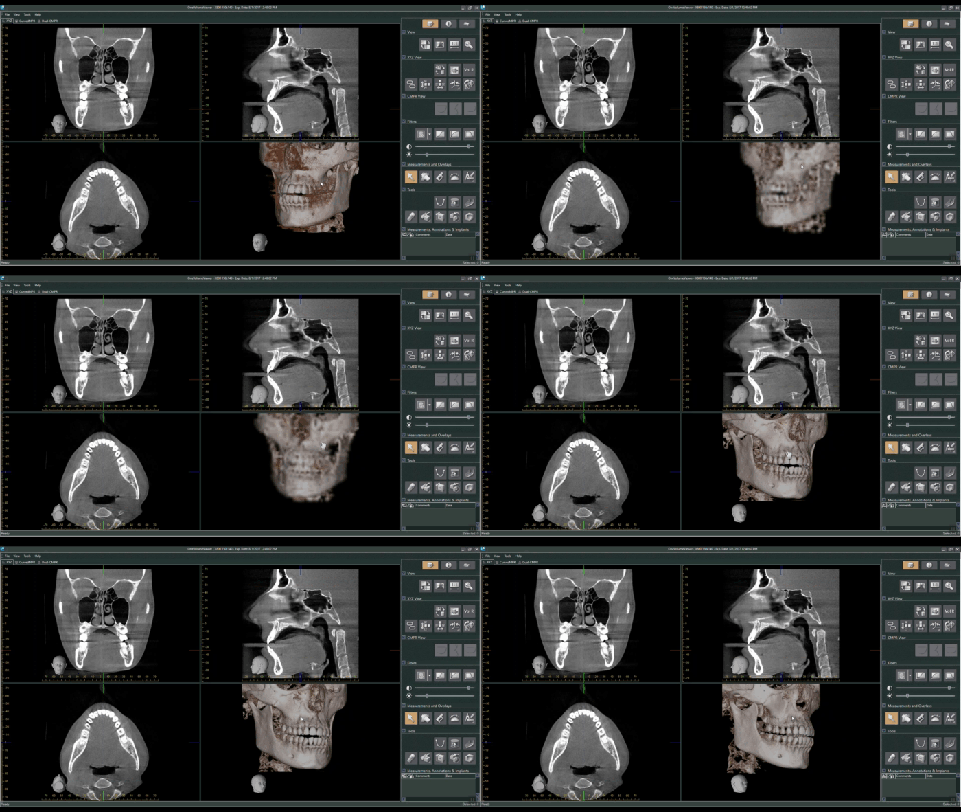
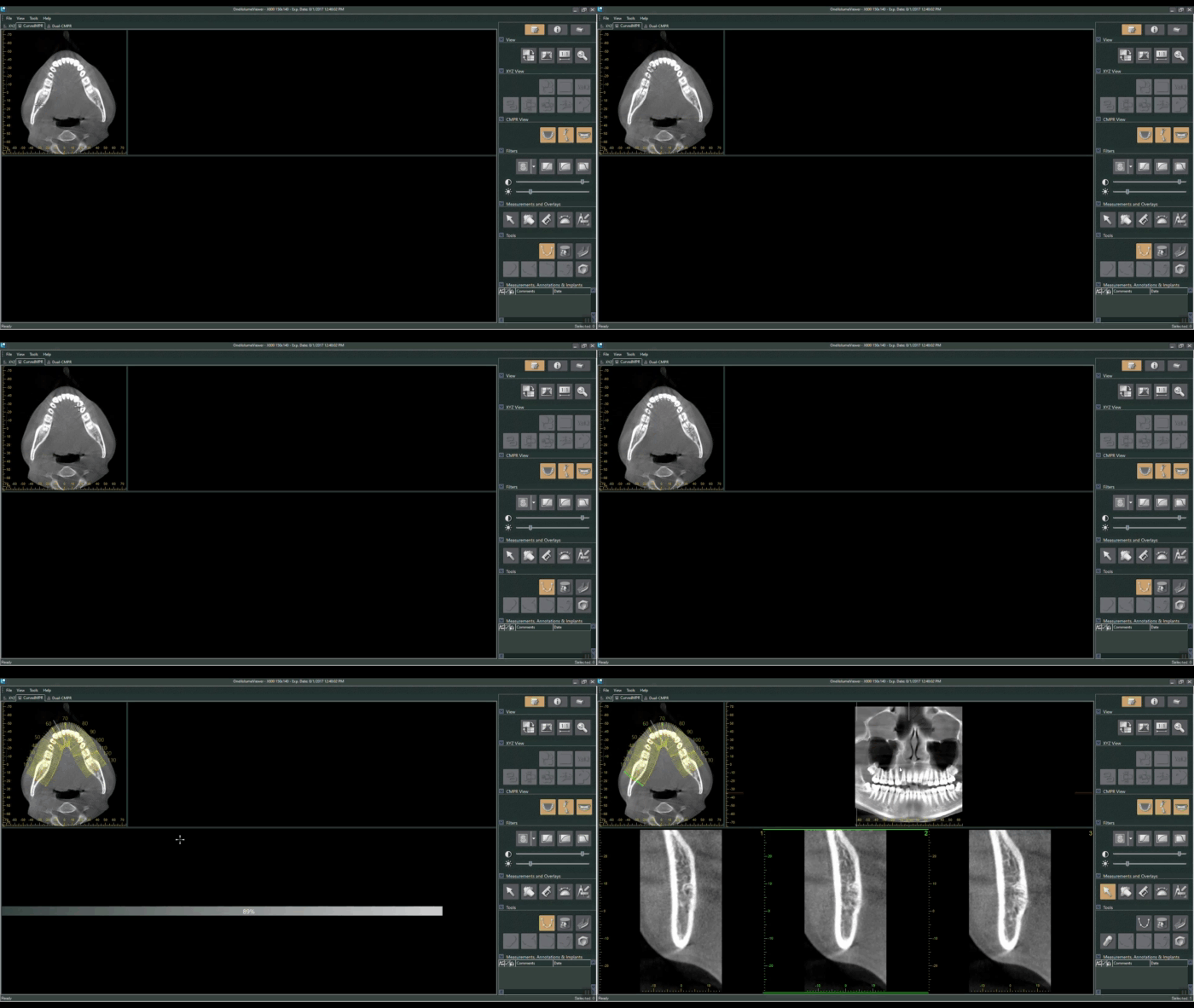
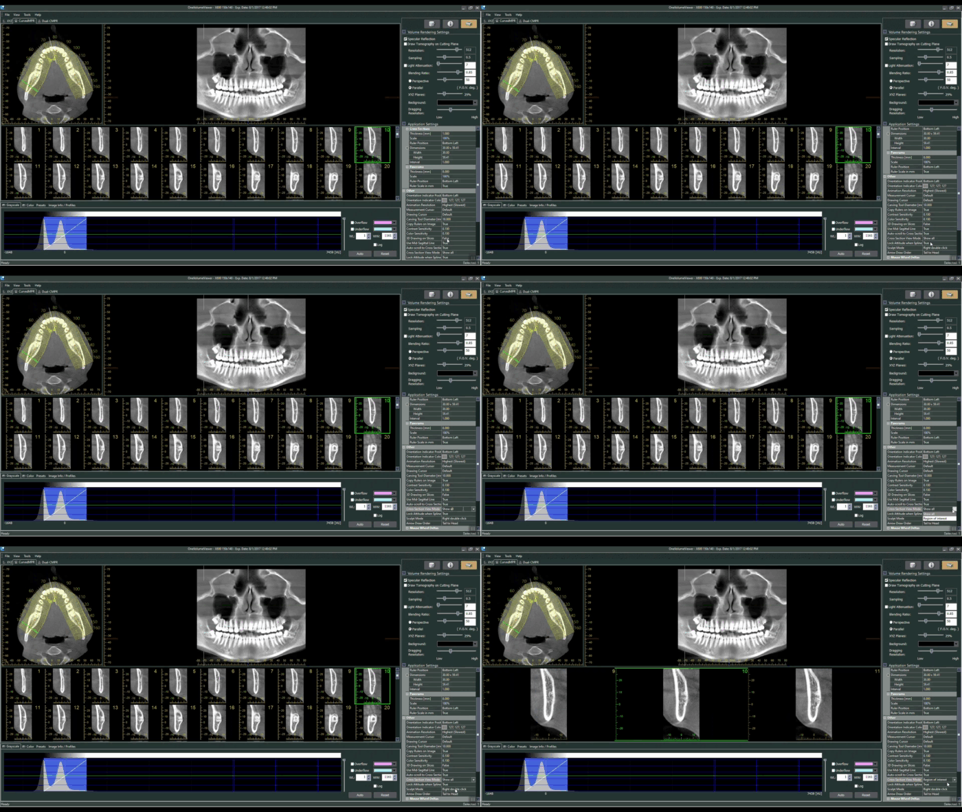
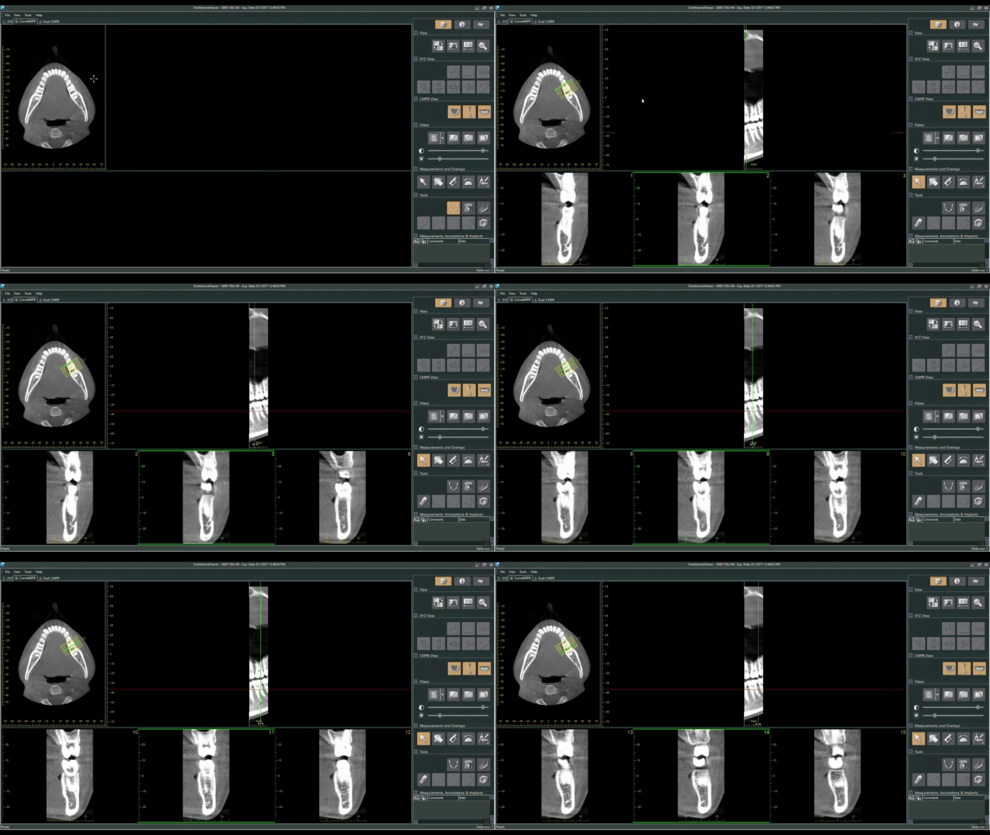
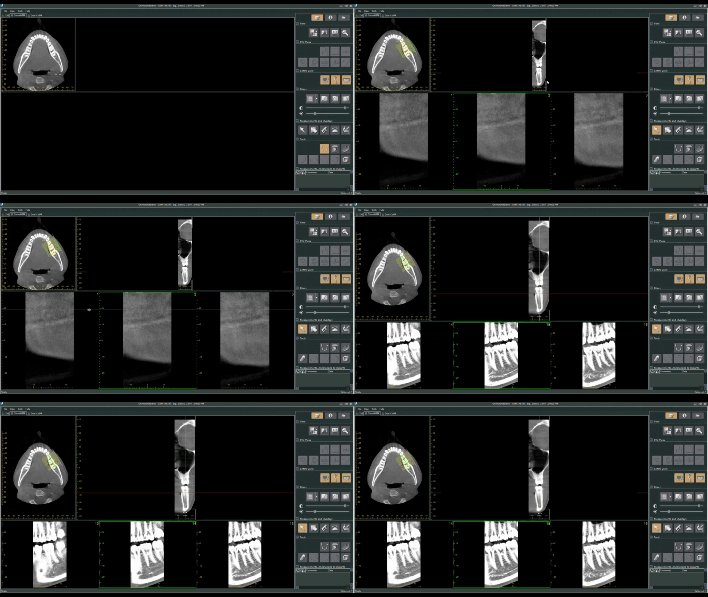
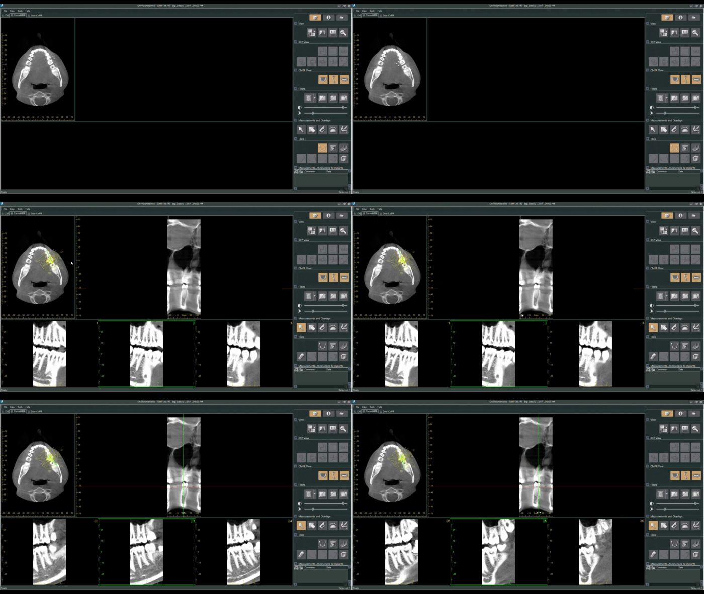
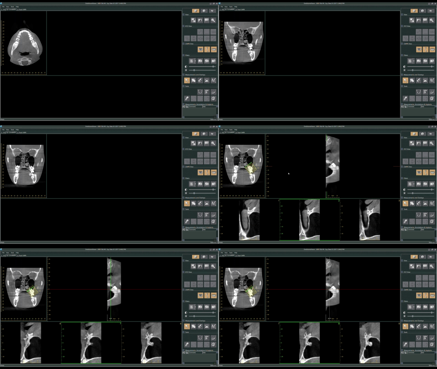
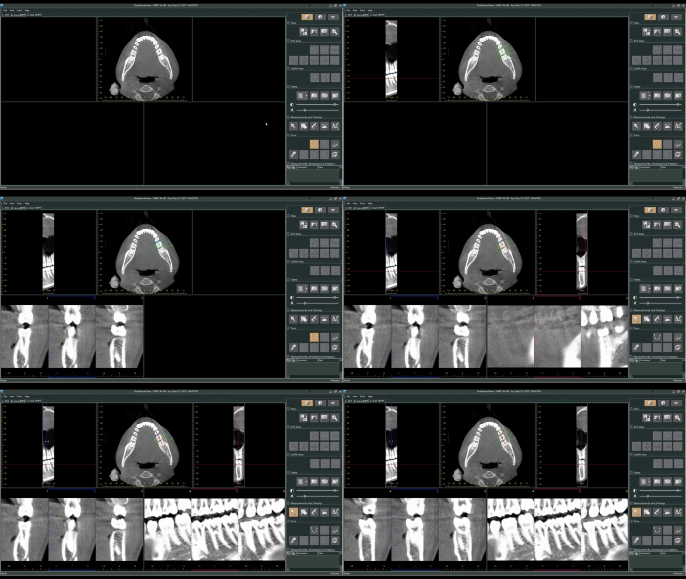
J. Morita's 3D viewing and treatment planning software, i-Dixel, offers a robust set of tools to review scans and plan treatment digitally. When a scan is loaded, the data is presented in the "volume view" with windows for axial, coronal, sagittal, and 3D perspectives: The MPR (Multi-Planar Reconstruction) and Dual-MPR tabs allow for different (and arguably more precise) perspective views to analyze a CBCT volume and plan treatment. In either MPR tab, the user draws an "MPR line/curve", along which the software places perpendicular "slices" at adjustable intervals which allow the user to progress through cross-sections of the patient's anatomy in a slice-by-slice perspective. This is a useful tool-- for example-- to analyze discrete regions of interest, trace the mandibular canal for implants, and verify the angle and depth of a planned implant. Below, we will explore some of the different views that can be created by tracing an MPR curve. Extracting a 2D Pan from a 3D VolumeBy tracing our MPR curve along the entire arch, the user is able to create an extracted panoramic image from their 3D volume. To the right of the axial view (in which the MPR curve is drawn), the software compiles a flattened or panoramic image of whatever anatomy the MPR curve spans. If one draws a curve that spans the entire arch, the software will give a panoramic view of the patient's mouth. *Useful Tip* The number of slices displayed in the bottom window can be adjusted by changing the "Cross Section View Mode" under the Settings section of the viewer: Mesial-DistalTracing an MPR-Curve along a single tooth, implant site, or a few teeth, will provide the user with coronal-perspective set of slices to progress through the mesial-distal aspects of the anatomy. This view is especially useful for mapping the mandibular canal for lower-arch implant cases. Buccal-LingualTracing an MPR line across a tooth or implant site from the buccal to lingual side will allow the user to progress through the area from a sagittal perspective: RadialThe MPR curve can also be drawn into a shape. Creating a circle around a tooth will allow the user to examine circumferential aspects of the targeted area: Root-Crown (Long Axis)The user is also able to rotate the axial view in the top-left window to a coronal perspective by clicking and dragging their mouse cursor. Drawing the MPR line from a tooth's root to its crown in this view will give us axial slices to progress through. This view can be very useful for locating missed canals, or examining teeth/implants that may have issues related to the patient's sinus cavity. Dual-MPRThe Dual-MPR tab allows the user to draw two MPR lines for two different slice-by-slice perspectives. Below, we draw a mesial-distal and buccal-lingual MPR curve to allow us to view the tooth through both coronal and sagittal slices. The Dual-MPR function is especially ideal for verifying the depth and angle of a planned implant from multiple perspectives. MPR curves can provide a more focused view of anatomical landmarks, and allow the user to create more diagnostic images for case presentation. For planning implants and mapping the mandibular canal, the MPR or Dual-MPR view is usually preferable to the volume view as they allow for a more precise view of the specific area.
Dental TI clients can connect with our staff for free one-on-one or team training on volume review and treatment planning functions in i-Dixel. Not a client? Feel free to request a free consultation to learn more about how Dental TI can help you get the most out of your imaging technology. Top Ten Technology Mistakes
Ten Keys To Successful Technology Implementation
Accurate positioning when acquiring a CBCT scan is critical to ensure the desired anatomy is captured and able to be reviewed. If a patient has restorations present in the mouth already, fine adjustments in positioning can make the difference between an easily readable or entirely non-diagnostic resulting volume. Larger FOV (field of view) scans are generally easier to position since most all CBCT units offer laser markers that give the technician a general sense of the anatomy that will be captured.
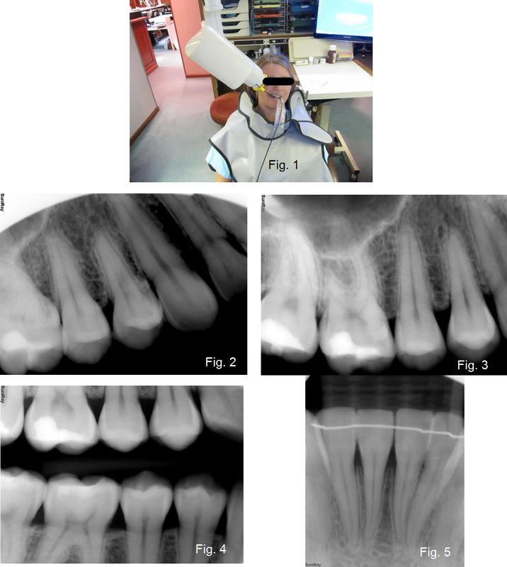
However, many offices find themselves wanting to capture a small FOV scan on a patient whose treatment plan focuses on a small area of the mouth, such as a single tooth or sextant. Small FOV scans are generally preferred for these situations as the dose to the patient is minimized, and the clinician mitigates risk by not imaging areas of anatomy beyond the region of interest (ROI). These sorts of scans are best acquired with software aided positioning functions, usually referred to as 'scouting'. Many CBCT units offer 'panoramic scout' functions where the operator captures a panoramic x-ray of the patient, then moves to the acquisition PC to define the desired ROI and submit the setting to the CT unit, and then finally returns to the exposure switch to capture the 'scouted' CBCT scan. Through this process, the patient must remain in position for the scan; a process that can easily take a couple of minutes as the panoramic image is captured and reconstructed, the operator sets the scout position, and then the 3D scan is acquired. J. Morita's X800 CBCT system introduced a new scouting method, the bi-directional scout, that saves time and reduces overall exposure to the patient while actually improving the accuracy of the scout. The region of interest is specified by taking lateral and frontal scout images in a single shot that completes in less than half the time of a traditional panoramic. These images are used to accurately position for a limited field CBCT exposure. The unit's touch console offers a pictograph of a dental arch that can be used to specify the general ROI before the patient enters the unit. The patient is then positioned, and the bi-directional scout is captured. This scout image returns in less than half the time it takes for a panoramic x-ray to return, allowing the operator to more quickly set the exact ROI and send it to the machine. Dental TI clients with the J. Morita X800 have enjoyed the bi-directional scout function to greatly reduce scan time and exposure dosage for their patients. Give us a call today at 1.800.672.5733 to learn more about J. Morita CBCT and how we can help you reduce downtime, boost profitability, and optimize diagnostic image quality. Everyone has heard the saying that a chain is only as strong as its weakest link. The same can be said for image quality with Digital X-rays. The imaging chain encompasses the radiation source, the positioning devices, sensor placement with such devices, the intraoral sensor, and the post processing algorithms. If any of the preceding is less than optimal than the diagnostic information will be obscured or artifacts can relate to misdiagnosis. The following is a general guideline to help offices optimize each link in the imaging chain for consistent, diagnostic information.
Consider the source – X-ray heads come in two flavors AC (alternating current) and DC (direct current) heads. In general most new heads are DC units which are generally better for digital x-ray due to the greater adjustability that DC heads offer over exposure variables. Digital x-rays produce the best images when exposed at 60-65kV. Higher kV levels can be used but image quality is typically compromised as the higher kV levels tend to create more high contrast variation with less gray scale. Post processing contrast adjustment tools can be used to compensate for higher kV levels. Regardless of the x-ray head that is being used, there will be three different x-ray exposures that will be required to achieve optimal results. The exposure levels vary due to the density of the area of the mouth. For each setting there will be a range (typically two incremental adjustments on the x-ray controller) that will accommodate different bone densities from a child to a large adult male. When determining the correct exposure level the following process works well:
|
Dental TI Technology TeamWe're happy to welcome you to our blog! Check out Archives
February 2020
Categories |
- Home
- Tech Support
- Promotions
- Products
-
LEARNING CENTER
- Blog
- Continuing Education >
- FAQ
- Leave a Review
- Testimonials
-
Videos
>
- Blue Sky Bio Training Videos
- Continuing Education VIdeos
- Dental TI Company Videos
- Eaglesoft Training Videos
- HDX Will CBCT Videos
- IntraOral Camera Training
- Intraoral Sensor Training
- i-Dixel
- J. Morita Products/Training >
- PreXion Products/Training
- PreXion3D Software Training
- Xray Vision Software Training
- About
- Contact
- Financing
- For Patients
- DTI Resources
1015 3rd Ave SW l Carmel, IN 46032 l 800.672.5733 l Contact Us
Copyright 2020 Dental Technology Integrators Inc.




 RSS Feed